vpdn что это такое
Vpdn что это такое
Представленная ниже страница, лишь часть огромного сайта посвященного различной компьютерной документации, на сайте собрано более 800 мб информации. Если Вы не нашли в этой статье, то что Вы ищите попробуте посмотреть здесь, cпросить на форуме или поискать необходимую Вам информацию в нашем каталоге ссылок сайтов компьтерной тематики.
Если же Вы хотите приобрести бумажную копию представленных здесь
материалов, обращайтесь в наш книжный магазин.
С уважением,
команда разработчиков eManual.ru
Виртуальные частные коммутируемые сети. Virtual Private Dialup Network (VPDN).
| Virtual Private Dialup Network (VPDN) Виртуальные частные коммутируемые сети Virtual Private Dialup Network (VPDN) |
Информацию о RFC упоминаемых в этом документе, смотрите: RFC поддерживаемые Cisco IOS Release 11.2 ; Комментарии к RFCs и другие документы о стандартах ; или RFC Index для выхода на прямую к InterNIC.
2.0 Краткий обзор VPDN
Рисунок 1: подключение jsmith к Серверу доступа
В терминологии VPDN, ISP является NAS и шлюз HP является шлюзом корпоративной ЛВС.
Рисунок 2: подключаение jsmith к шлюзу HP используя VPDN.
Следующие секции описывают некоторые аспекты L2F.
Здесь описываются перспективы PPP и L2F. Для более подробного изучения данного вопроса обратитесь к RFC L2F.
2.1.1 PPP Авторизация
Последовательность начинается с описания поступающей PPP сессией на NAS от клиента. После фазы LCP обменов, начинается стадия PPP авторизации на NAS. NAS посылает CHAP запросы клиенту. Клиент, в свою очередь, возвращает CHAP ответ.
После получения этого ответа, NAS определяет соответствие имени пользователя конфигурации, по которой нужно использовать VPDN, чтобы переправить PPP-сессию на шлюз корпоративной сети. В этом случае, так как это первая L2F сессия к корпоративному шлюзу, NAS и локальный шлюз обмениваются пакетами L2F туннелирования. Именно на стадии L2F туннель между NAS и корпоративным шлюзом закончен. Когда L2F тунелирование закончено, NAS и корпоративный шлюз обмениваются пакетами(Mid) L2F сессии. Пакеты L2F_OPEN (Mid) от NAS Корпоративному шлюзу несут LCP информацию, CHAP запрос и ответ на него.
В корпоративном шлюзе LCP информация сессии LCP переправляется в виртуальный интерфейс доступа, созданный для L2F сессии. CHAP запрос и ответ заверяются корпоративным шлюзом. Например, послано CHAP сообщение: Auth-OK.
Поскольку, поскольку клиент авторизован, после получения ответа Auth-OK, PPP закончил стадию LCP авторизации. После этого возможен скрытый обменен между клиентом и корпоративным шлюзом. NAS невидим для PPP структуры.
Последующие сеансы PPP ( для того же самого шлюза) повторяют обмен сеанса L2F, т.к. уже существует L2F тунель, сформированный к корпоративному шлюзу.
Рисунок 3. PPP Aвторизация
2.1.2 Авторизация L2F туннелирования
Рисунок 4. Авторизация L2F туннелирования
3.0 Конфигурация VPDN 3.1 Простая конфигурация
Клиент jsmith: hostname jsmith@hp.com
! Username and password of NAS challenging this client
username isp password test
Если некоторые клиенты используют Multilink PPP (MP), а некоторые нет, то самая простая конфигурация должна быть готова к MP на NAS и Корпоратывном шлюзе. Обратите внимание, что нет никакой потребности определять команду виртуального шаблона MP.
По умолчанию, NAS вызывает клиента, клиент посылает ответ на NAS, который использует L2F, чтобы туннелировать опознавательную информацию корпоративному шлюзу, которым авторизация будет решена. Корпоративный шлюз не посылает CHAP запрос клиенту. Если требуется, чтобы был послан CHAP запрос от корпоративного шлюза, используется команда:
At the client, you will need to prepare for the CHAP challenge now arriving from hp-gw: Client jsmith@hp.com:
username hp-gw password test 3.4 Двунаправленный CHAP
Двунаправленный CHAP поддерживается в VPDN. Пример конфигурации (продолжение предыдущего):
int s0 ppp authen chap 3.5 Пример конфигурации AAA (Authorization, and Accounting)
На NAS, AAA может использоваться, чтобы решить, использовать ли VPDN для специфического домена.
3.5.1 Используя TACACS+ NAS isp: aaa new-model aaa authentication ppp default tacacs+ aaa authorization network tacacs+ local tacacs-server host 2.2.2.2 no tacacs-server directed-request tacacs-server key bulldog TACAC+ записи: user = hp.com < service = ppp protocol = vpdn < tunnel-id = isp ip-addresses = "1.1.1.2" nas-password = "hello" gw-password = "there" >>
Последние две записи дополнительные. Они могли быть определены отдельно:
user = isp < : chap = cleartext "hello" >> user = hp-gw < : chap = cleartext "there" >> Корпоративный шлюз hp-gw: aaa new-model aaa authentication ppp default tacacs+ aaa authorization network tacacs+ local tacacs-server host 3.3.3.3 no tacacs-server directed-request tacacs-server key unleash TACAC+ записи: user = isp < : chap = cleartext "hello" >> user = hp-gw < : chap = cleartext "there" >> user = jsmith@hp.com < : chap = cleartext "test" >> 3.5.2 Используя Radius NAS isp: aaa new-model aaa author network radius aaa authen ppp default radius local radius-server host 2.2.2.2 radius-server key malibu
Записи Radius: hp.com Password = «cisco», User-Service-Type = Outbound-User cisco-avpair = «vpdn:tunnel-id=hp-gw», cisco-avpair = «vpdn:ip-addresses=1.1.1.2», cisco-avpair = «vpdn:nas-password=hello», cisco-avpair = «vpdn:gw-password=there»
Последние два дополнительные записи. Они могли быть определены локально на NAS.
3.6 Исходный адрес VPDN
Эта опция позволяет NAS определить исходный IP-адрес NAS. Когда это определено, пакеты L2F к корпоративному шлюзу всегда имеют его как исходный IP-адрес.
NAS isp: #config vpdn vpdn source-ip 1.1.1.4 3.7 Множественный адрес назначения VPDN
3.8 VPDN поверх Frame Relay
3.9 VPDN DNIS (Dialed Number Information Service )
NAS isp: #config vpdn outgoing dnis 1234567 isp ip 1.1.1.2 AAA: Используя TACACS+ или Radius:
Вводится запись «dnis:1234567» (как, любое другое имя пользователя).
Получение отладочной информации: debug information:pdn event Se0:21 VPN got DNIS string 1234567 from ISDN
Обратите внимание: неявно что, если AAA не доступно или не соответствует для DNIS туннеля, VPDN будет искать любые существующие конфигурации VPDN на NAS для имени домена. Короче говоря, специфика DNIS предшествует общему соответствию для имени домена.
Vpdn что это такое
VPDN означает remote access и циска реализует его на несколько странной модели, общая схема которой представлена на рисунке ниже. NAS – это некий сервер, реализующий для юзера услуги связи – выход в инет, создание туннеля от себя до роутера компании (до ТС’а). ТС – это девайс, терминирующий на себе туннели от NAS‘ов для входа в сеть компании.
Здесь юзер через PSTN дозванивается до ISP и аутентифицируется на его NAS‘е. Затем NAS провайдера должен установить туннель с туннельным сервером, чтобы клиент мог безопасно попасть в свою корпоративную сеть. Итак, получается, что NAS это вовсе не тот сервак, на котором юзер терминирует свой PPTP, более того юзер сам вообще не инициирует создание PPTP туннеля. С точки зрения циски NAS – это машина, которая инициирует создание РРТР туннеля, обращаясь к ТС, т.е. туннель терминируется на ТС. NAS получает «звонок» от юзера (для NAS’а это dialin), затем он обращается к ТС’у c «запросом» создать туннель для трафа этого dialin соединения (request-dialin). NAS расценивает все звонки от своих клиентов как dialin. ТС тоже считает, что dialin – это звонки, поступившие на NAS. Однако, если ТС инициирует создание туннеля в сторону NAS’а, то это для ТС’а dialout, и NAS знает, что dialout – это инициация туннеля ТС’ом. Итак, теперь можно всё свести в единую таблицу, указав команды, которые применяются на NAS’е и ТС’е:
| Команды NAS’а | Команды ТС’а |
| request-dialin: позволяет NAS’у запрашивать ТС’а, чтобы тот поднимал туннель, для трафа dialin звонка, поступившего на NAS.. | accept-dialin: позволяет ТС’у поднимать туннель по запросуNAS’а. |
| accept-dialout: позволяет NAS’у поднимать туннель по запросу ТС’а. | request-dialout: позволяет ТС’у запрашивать NAS, чтобы тот поднимал туннель, инициированный ТС’ом |
ИТ База знаний
Полезно
— Онлайн генератор устойчивых паролей
— Онлайн калькулятор подсетей
— Руководство администратора FreePBX на русском языке
— Руководство администратора Cisco UCM/CME на русском языке
— Руководство администратора по Linux/Unix
Навигация
Серверные решения
Телефония
FreePBX и Asterisk
Настройка программных телефонов
Корпоративные сети
Протоколы и стандарты
Настройка PPTP на маршрутизаторах Cisco
Прямиком в туннель
PPTP (Point to Point Protocol), или, если дословно перевести, тунельный протокол типа точка-точка, является простым и быстрым решением по предоставлению удаленного доступа для пользователей. Данный протокол нативно поддерживается на операционных системах Windows XP, 7, 8, и так далее, что делает его идеальным решением для большинства офисных работников – он, к тому же, не требует установки никакого дополнительного ПО.
Онлайн курс по Кибербезопасности
Изучи хакерский майндсет и научись защищать свою инфраструктуру! Самые важные и актуальные знания, которые помогут не только войти в ИБ, но и понять реальное положение дел в индустрии
Главное, что нужно понимать: PPTP не обладает сильным шифрованием и прочими «фишками», которые предлагают IPSEC или SSL VPN решения. Несмотря на то, что MPPE (Microsoft Point-to-Point Encryption), поддерживаемый маршрутизаторами Cisco предоставляет довольно высокую степень защищенности, все равно не должен использоваться в сценариях, когда предоставляется доступ к ценной и/или конфиденциальной информации.
Как и в других решениях, предоставляющих удаленный доступ, удаленный пользователь может использовать PPTP для доступа к корпоративной сети и, по сути, он будет подключен прямо к внутренней подсети.
PPTP всегда настраивается между сервером (маршрутизатором Cisco) и клиентом (рабочей станцией Windows). PPTP поддерживается маршрутизаторами Cisco, а МСЭ ASA, в свою очередь, не поддерживают терминирование туннеля на самом фаерволле.
Процесс настройки клиента легко ищется в интернете, данная же статья описывает настройку маршрутизатора.
Сценарий и схема сети
В данной статье у нас предполагается следующий сценарий: к корпоративной сети принадлежит несколько филиалов, соединенных через VPN (к примеру, MPLS VPN, IPSEC VPN и так далее). Главный офис подключен к интернету и мы реализиуем простой и быстрый способ подключения удаленных пользователей к данной сети.
Допустим, интерфейс VLAN 1 (подсеть 10.10.10.0/24) маршрутизируется в основной сети. Если мы «подключим» удаленных пользователей через PPTP туннель к данному VLAN и назначим адрес из диапазона 10.10.10.0/24, то, логично, что у них появится доступ ко всем сетевым ресурсам.
В данном случае аутентификация будет реализована через локальные аккаунты на маршрутизаторе Cisco. Однако, в соответствии с рекомендациями по безопасности, мы рекомендуем использовать внешний RADIUS cервер. Оборудованием в нашем гипотетическом случае является 867VAE-K9 с образом c860vae-advsecurityk9-mz.152-4.M3.bin.
PPTP всегда настраивается между сервером (маршрутизатором Cisco) и клиентом (рабочей станцией Windows). PPTP поддерживается маршрутизаторами Cisco, а МСЭ ASA, в свою очередь, не поддерживают терминирование туннеля на самом фаерволле.
Настройка маршрутизатора
Ниже приведен пример конфига, с комментариями почти после каждой команды.
Далее, обратите внимание на настройку интерфейсов (очевидные и всем известные команды):
Далее, попробуйте подключить какой-нибудь клиент и проверьте работоспособность PPTP командами:
Полный курс по Сетевым Технологиям
В курсе тебя ждет концентрат ТОП 15 навыков, которые обязан знать ведущий инженер или senior Network Operation Engineer
Understanding VPDN
Available Languages
Download Options
Contents
Introduction
A virtual private dial-up network (VPDN) allows a private network dial in service to span across to remote access servers (defined as the L2TP Access Concentrator [LAC]).
When a Point-to-Point Protocol (PPP) client dials into a LAC, the LAC determines that it should forward that PPP session on to an L2TP Network Server (LNS) for that client. The LNS then authenticates the user and starts the PPP negotiation. Once PPP setup has completed, all frames are sent through the LAC to the client and the LNS.
Prerequisites
Requirements
There are no specific requirements for this document.
Components Used
This document is not restricted to specific software and hardware versions.
The information presented in this document was created from devices in a specific lab environment. All of the devices used in this document started with a cleared (default) configuration. If you are working in a live network, ensure that you understand the potential impact of any command before using it.
Conventions
For more information on document conventions, refer to the Cisco Technical Tips Conventions.
Glossary
Client: PC or router attached to a remote access network, which is the initiator of a call.
L2TP: Layer 2 Tunnel Protocol. PPP defines an encapsulation mechanism for transporting multiprotocol packets across layer 2 (L2) point-to-point links. Typically, a user obtains an L2 connection to a Network Access Server (NAS) using a technique such as dialup plain old telephone service (POTS), ISDN or Asymmetric Digital Subscriber Line (ADSL). The user then runs PPP over that connection. In such a configuration, the L2 termination point and PPP session endpoint reside on the same physical device (the NAS).
L2TP extends the PPP model by allowing the L2 and PPP endpoints to reside on different devices interconnected by a network. With L2TP, the user has an L2 connection to an access concentrator, and the concentrator then tunnels individual PPP frames to the NAS. This allows the actual processing of PPP packets to be divorced from the termination of the L2 circuit.
L2F: Layer 2 Forwarding Protocol. L2F is a tunneling protocol older than L2TP.
LAC: L2TP Access Concentrator. A node that acts as one side of an L2TP tunnel endpoint and is a peer to the LNS. The LAC sits between an LNS and a client and forwards packets to and from each. Packets sent from the LAC to the LNS require tunneling with the L2TP protocol. The connection from the LAC to the client is typically through ISDN or analog.
LNS: L2TP Network Server. A node that acts as one side of an L2TP tunnel endpoint and is a peer to the LAC. The LNS is the logical termination point of a PPP session that is being tunneled from the client by the LAC.
Home Gateway: Same definition as LNS in L2F terminology.
NAS: Same definition as LAC in L2F terminology.
Tunnel: In L2TP terminology, a tunnel exists between a LAC-LNS pair. The tunnel consists of a control connection and zero or more L2TP Sessions. The tunnel carries encapsulated PPP datagrams and control messages between the LAC and the LNS. The process is the same for L2F.
Session: L2TP is connection-oriented. The LNS and LAC maintain a state for each call that is initiated or answered by an LAC. An L2TP session is created between the LAC and LNS when an end-to-end PPP connection is established between a client and the LNS. Datagrams related to the PPP connection are sent over the tunnel between the LAC and LNS. There is a one-to-one relationship between established L2TP sessions and their associated calls. The process is the same for L2F.
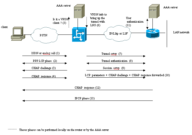
Overview of the VPDN Process
In the description of the VPDN process below, we use the L2TP terminology (LAC and LNS).
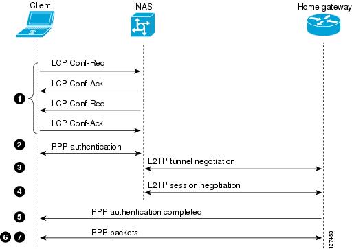
The client calls the LAC (typically using a modem or an ISDN card).
The client and the LAC starts the PPP phase by negotiating the LCP options (authentication method Password Authentication Protocol [PAP] or Challenge Handshake Authentication Protocol [CHAP], PPP multilink, compression, and so on).
Let’s suppose that CHAP has been negotiated in step 2. The LAC sends a CHAP challenge to the client.
The LAC gets a response (for instance username@DomainName and password).
Based on the domain name received in the CHAP response or the Dialed Number Information Service (DNIS) received in the ISDN setup message, the LAC checks whether the client is a VPDN user. It does this by using its local VPDN configuration or contacting an Authentication, Authorization, and Accounting (AAA) server.
Because the client is a VPDN user, the LAC gets some information (from its local VPDN configuration or from an AAA server) that it uses to bring up a L2TP or L2F tunnel with the LNS.
The LAC brings up a L2TP or L2F tunnel with the LNS.
Based on the name received in the request from the LAC, the LNS checks if the LAC is allowed to open a tunnel (the LNS checks its local VPDN configuration). Moreover, the LAC and the LNS authenticate each other (they use their local database or contact an AAA server). The Tunnel is then up between both devices. In this tunnel, several VPDN sessions can be carried.
For the client username@DomainName, a VPDN session is triggered from the LAC to the LNS. There is one VPDN session per client.
The LAC forwards the LCP options it has negotiated to the LNS with the client along with the username@DomainName and password received from the client.
The LNS clones a virtual-access from a virtual-template specified in the VPDN configuration. The LNS takes the LCP options received from the LAC and authenticate the client locally or by contacting the AAA server.
The LNS sends a CHAP response to the client.
The IP Control Protocol (IPCP) phase is performed and then the route is installed: the PPP session is up and running between the client and the LNS. The LAC just forwards the PPP frames. The PPP frames are tunneled between the LAC and the LNS.
Tunneling Protocols
A VPDN tunnel can be built using either Layer-2 Forwarding (L2F) or Layer-2 Tunneling Protocol (L2TP).
L2F was introduced by Cisco in Request For Comments (RFC) 2341 and is also used to forward PPP sessions for Multichassis Multilink PPP.
L2TP, introduced in RFC 2661, combines the best of the Cisco L2F protocol and Microsoft Point-to-Point Tunneling Protocol (PPTP). Moreover, L2F supports only dial-in VPDN while L2TP supports both dial-in and dial-out VPDN.
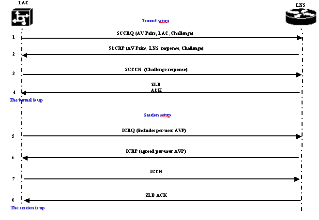
Both protocols use the UDP port 1701 to build a tunnel through an IP network to forward link-layer frames. For L2TP, the setup for tunneling a PPP session consists of two steps:
Establishing a tunnel between the LAC and the LNS. This phase takes place only when there is no active tunnel between both devices.
Establishing a session between the LAC and the LNS.
The LAC decides that a tunnel must be initiated from the LAC to the LNS.
The LAC sends a Start-Control-Connection-Request (SCCRQ). A CHAP challenge and AV Pairs are included in this message.
The LNS responds with a Start-Control-Connection-Reply (SCCRP). A CHAP challenge, the response to LAC’s challenge and AV Pairs are included in this message.
The LAC sends a Start-Control-Connection-Connected (SCCCN). The CHAP response is included in this message.
The LNS responds with a Zero-Length Body Acknowledgement (ZLB ACK). That acknowledgement may be carried in another message. The tunnel is up.
The LAC sends an Incoming-Call-Request (ICRQ) to the LNS.
The LNS responds with an Incoming-Call-Reply (ICRP) message.
The LAC sends an Incoming-Call-Connected (ICCN).
The LNS responds back with a ZLB ACK. That acknowledgement may also be carried in another message.
Note: The messages above used for opening a tunnel or a session carry Attribute Value Pairs (AVPs) defined in RFC 2661. They describe properties and information (such as Bearercap, hostname, vendor name and window size). Some AV pairs are mandatory and others are optional.
Note: A Tunnel ID is used to multiplex and demultiplex tunnels between the LAC and LNS. A session ID is used to identify a particular session with the tunnel.
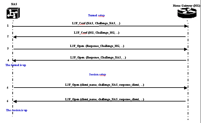
For L2F, the setup for tunneling a PPP session is the same as for L2TP. It involves:
Establishing a tunnel between the NAS and the Home Gateway. This phase takes place only when there is no active tunnel between both devices.
Establishing a session between the NAS and the Home Gateway.
The NAS decides that a tunnel must be initiated from the NAS to the Home Gateway.
The NAS sends a L2F_Conf to Home Gateway. A CHAP challenge is included in this message.
The Home Gateway responds with a L2F_Conf. A CHAP challenge is included in this message.
The NAS sends a L2F_Open. The CHAP response of the Home Gateway challenge is included in this message.
The Home Gateway responds with a L2F_Open. The CHAP response of the NAS challenge is included in this message. The tunnel is up.
The NAS sends a L2F_Open to the Home Gateway. The packet includes the username of the client (client_name), the CHAP challenge sent by the NAS to the client (challenge_NAS) and its response (response_client).
The Home Gateway, by sending back the L2F_OPEN, accepts the client. Traffic is now free to flow in either direction between the client and the Home Gateway.
Note: A tunnel is identified with a CLID (Client ID). Multiplex ID (MID) identifies a particular connection within the tunnel.
Configuring VPDN
For information on configuring VPDN, refer to the Configuring Virtual Private Networks manual, and go to the section on Configuring VPN.
VPDN Configuration Guide
Book Title
VPDN Configuration Guide
Chapter Title
VPDN Technology Overview
View with Adobe Reader on a variety of devices
Results
Chapter: VPDN Technology Overview
VPDN Technology Overview
Virtual private dial-up networks (VPDNs) securely carry private data over a public network, allowing remote users to access a private network over a shared infrastructure such as the Internet. VPDNs maintain the same security and management policies as a private network, while providing a cost-effective method for point-to-point connections between remote users and a central network.
Finding Feature Information
Your software release may not support all the features documented in this module. For the latest caveats and feature information, see Bug Search Tool and the release notes for your platform and software release. To find information about the features documented in this module, and to see a list of the releases in which each feature is supported, see the feature information table at the end of this module.
Use Cisco Feature Navigator to find information about platform support and Cisco software image support. To access Cisco Feature Navigator, go to www.cisco.com/go/cfn. An account on Cisco.com is not required.
Information About VPDNs
Overview of VPDN Technology
VPDNs extend private network dial-in services to remote users. VPDNs use Layer 2 tunneling technologies to create virtual point-to-point connections between remote clients and a private network. VPDNs maintain the same security and management policies as a private network, while providing a cost-effective method for point-to-point connections between remote users and a central network.
Instead of connecting directly to the remote private network, VPDN users connect to a nearby access server, which is often located at an Internet service provider (ISP) local point of presence (POP). Data is securely forwarded from the access server to the private network over the Internet, providing a cost-effective method of communication between remote clients and the private network.
A benefit of VPDNs is the way they delegate responsibilities for the network. The customer can outsource responsibility for the information technology (IT) infrastructure to an ISP that maintains the modems that the remote users dial in to, the access servers, and the internetworking expertise. The customer is then responsible only for authenticating users and maintaining the private network.
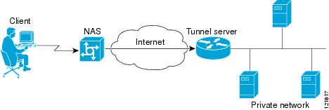
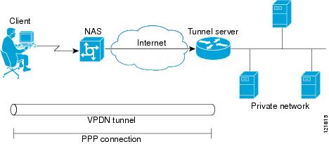
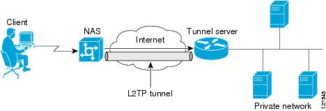
The figure below shows a basic VPDN network deployment.
Figure 1. Basic VPDN Network Deployment
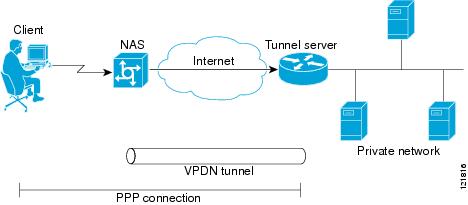
A PPP client dials in to an ISP access server, called the Network Access Server (NAS). The NAS determines whether it should forward that PPP session on to the router or access server that serves as the point of contact for the private network, the tunnel server. The tunnel server authenticates the user and initiates PPP negotiations. Once PPP setup is complete, all frames that are sent between the client and the tunnel server pass through the NAS.
VPDNs can use these tunneling protocols to tunnel link-level frames:
Layer 2 Tunneling Protocol (L2TP)
Layer 2 Tunneling Protocol Version 3 (L2TPv3)
Layer 2 Forwarding (L2F)
Point-to-Point Tunneling Protocol (PPTP)
Using one of these protocols, a tunnel is established between the NAS or client and the tunnel server, providing secure data transport over a shared infrastructure such as the Internet.


